-15%
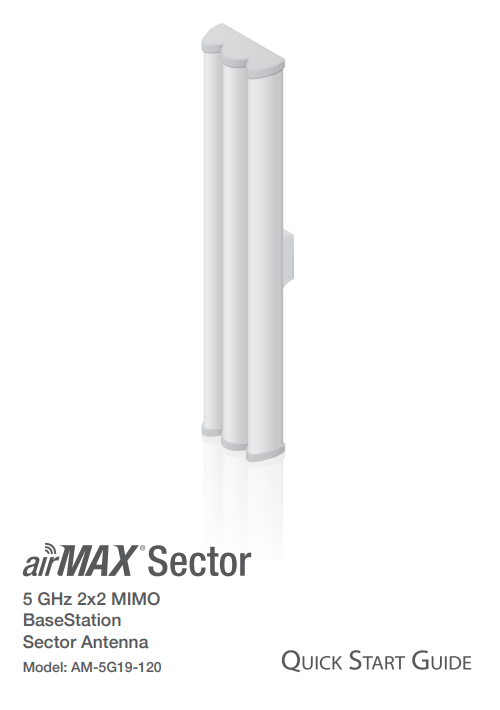
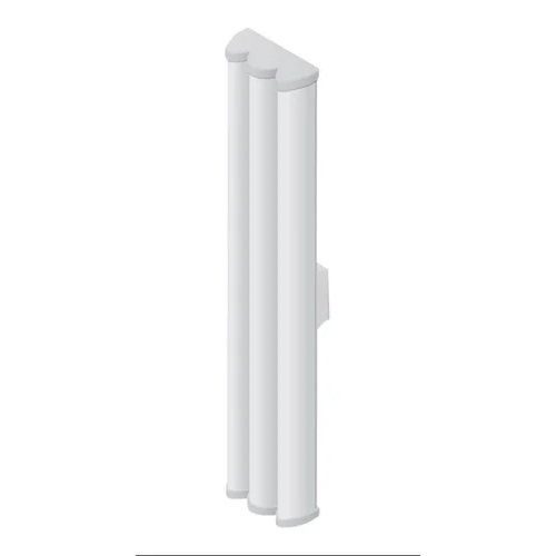

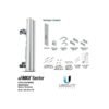
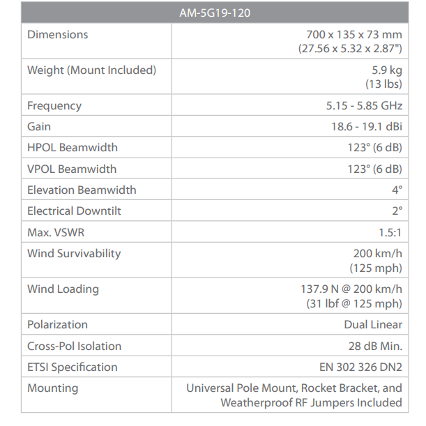
Ubiquiti Air Max 19dBi 5GHz Sector Antenna (AM-5G19-120)

Original price was: ₹18,900.00.₹15,999.00Current price is: ₹15,999.00.
Introduction
Thank you for purchasing the Ubiquiti Networks™ airMAX® 5 GHz 2×2 MIMO BaseStation Sector Antenna.
This Quick Start Guide is designed to guide you through the installation of the antenna.
This Quick Start Guide also includes the warranty terms and is for use with the airMAX Sector Antenna, model AM-5G19-120.
Ubiquiti Air Max 19dBi 5GHz Sector Antenna (AM-5G19-120)
The AM-5G19-120 AirMAX 5 GHz 2×2 MIMO Sector Antenna from Ubiquiti Networks provides networking flexibility and convenience by letting you create a customized base station with an optional RocketM radio. This antenna operates under the 5 GHz frequency and offers a gain of 19 dBi. It delivers 2×2 MIMO performance and supports airMAX
Installation Requirements
• Rocket M5 or RocketM5 GPS (sold separately)
• 12 mm and 13 mm wrenches
• Shielded Category 5 (or above) cabling should be used for all wired Ethernet connections and should be grounded
through the AC ground of the PoE.
We recommend that you protect your networks from the most brutal environments and devastating ESD attacks with industrial‑grade shielded Ethernet cable from Ubiquiti Networks. For more details, visit www.ubnt.com/toughcable

Hardware Installation
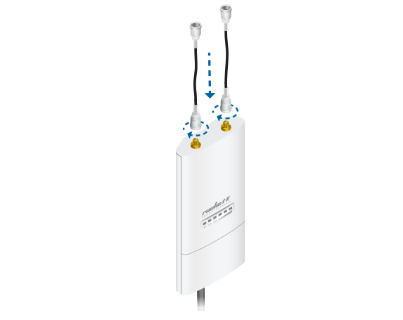
1. Attach the RF Cables to the connectors labeled Chain 0 and Chain 1 on the Rocket.
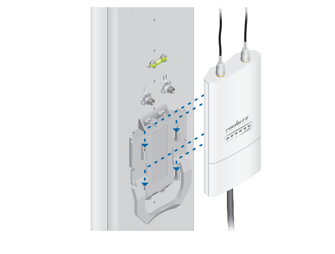
2. Attach the Rocket to the Rocket Mount Bracket.
a. Align the mounting tabs on the back of the Rocket with the four mounting slots on the bracket.
b. Slide the Rocket down until it locks into place.
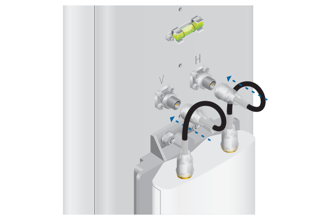
3. Connect the other ends of the RF Cables to the RF Connectors on the antenna.
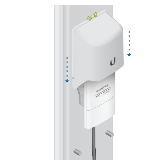
4. Slide the Protective Shroud down over the Rocket until it locks onto the Rocket Mount Bracket.
Note: If you have difficulty locking the shroud into place, try adjusting the placement of the RF Cables.
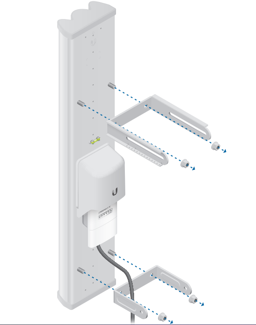
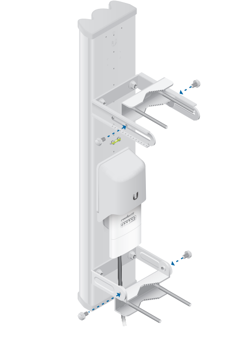
5. Attach the U-Brackets to the antenna: a. Secure the Slotted U-Bracket to the upper Mounting Lugs of the antenna using two Serrated Flange Nuts.
b. Secure the other U-Bracket to the lower Mounting Lugs of the antenna using two Serrated Flange Nuts.
Note: Orient both U-Brackets as shown below.
6. Insert two Carriage Bolts into each Pole Bracket.
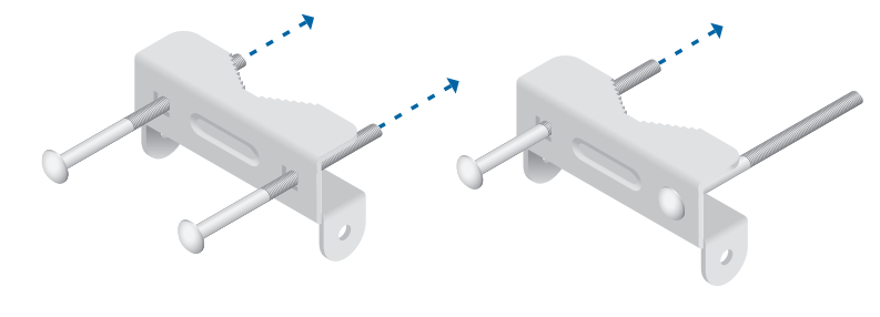
7. Attach each Pole Bracket to each U-Bracket using two Serrated Flange Bolts. Hand-tighten the bolts.
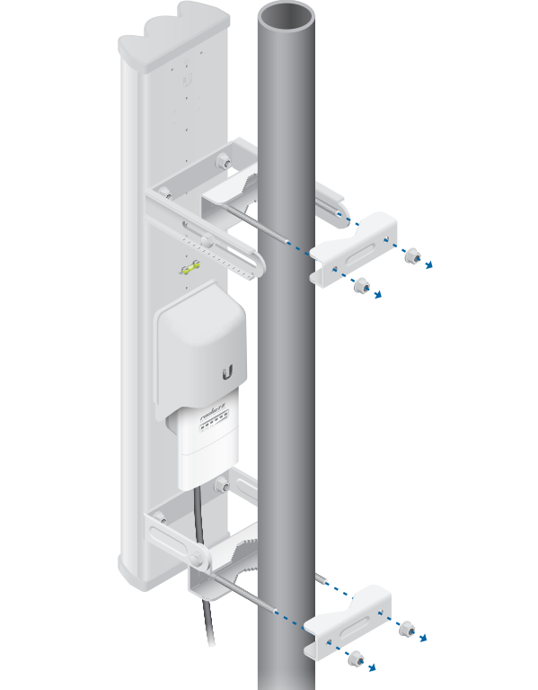
8. To mount the antenna to the pole, slide a Pole Clamp over each pair of Carriage Bolts. Secure each Pole Clamp with two Serrated Flange Nuts.
Note: The mounting assembly can accommodate a Ø 40 mm – 80 mm pole.
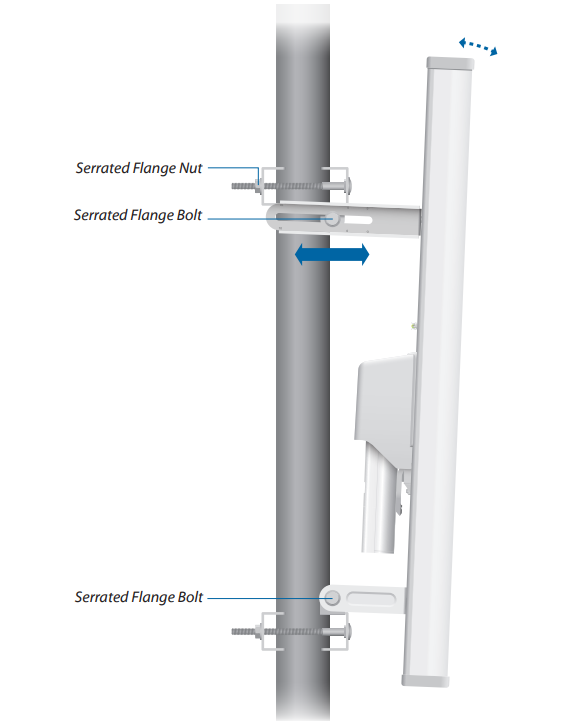
9. The antenna has an electrical downtilt of 2°. To further adjust the elevation angle:
a. Loosen the four Serrated Flange Bolts on the U-Brackets and the two Serrated Flange Nuts on the upper Pole Clamp.
b. Slide the antenna to the desired tilt. (The brackets may slide along the pole, depending on the angle of the elevation tilt.)
c. Tighten all bolts and nuts to approximately 25 N-m.
Specifications
Only logged in customers who have purchased this product may leave a review.
Related products


-15%

Access Points / CPE
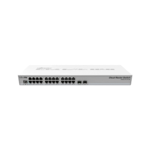
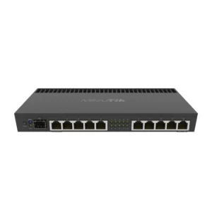
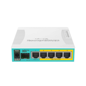
MikroTik RB4011iGS+RM – Powerful 10-Port Gigabit Router with SFP+
Original price was: ₹21,500.00.₹18,254.00Current price is: ₹18,254.00.


-16%


WIFI ROUTER / REPETER
SYROTECH SY-AX-1800 Wi-Fi 6 Gigabit Router with 5 High-Gain Antennas, Dual Band
Original price was: ₹5,800.00.₹4,900.00Current price is: ₹4,900.00.

-20%

Access Points / CPE
Original price was: ₹8,900.00.₹7,100.00Current price is: ₹7,100.00.
-20%
Access Points / CPE
Original price was: ₹9,000.00.₹7,220.00Current price is: ₹7,220.00.
-20%
Access Points / CPE
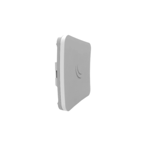
Mikrotik SXTsq 5 RBSXTsq5nD – Powerful 5 GHz Outdoor CPE for Long-Range Wireless
Original price was: ₹5,500.00.₹4,400.00Current price is: ₹4,400.00.
-14%


Access Points / CPE
Original price was: ₹7,900.00.₹6,800.00Current price is: ₹6,800.00.


-13%
Access Points / CPE
Mikrotik LHG XL HP5 RBLHG-5HPnD-XL – Long-Range 5 GHz Wireless CPE for Outdoor Networks
Original price was: ₹12,000.00.₹10,400.00Current price is: ₹10,400.00.
-15%

Access Points / CPE
Original price was: ₹8,500.00.₹7,200.00Current price is: ₹7,200.00.
-34%


WIFI ROUTER / REPETER
Original price was: ₹3,200.00.₹2,100.00Current price is: ₹2,100.00.


-19%

Access Points / CPE
Original price was: ₹7,700.00.₹6,200.00Current price is: ₹6,200.00.
Reviews
There are no reviews yet.